Features


Features

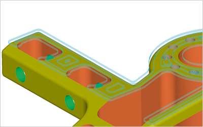
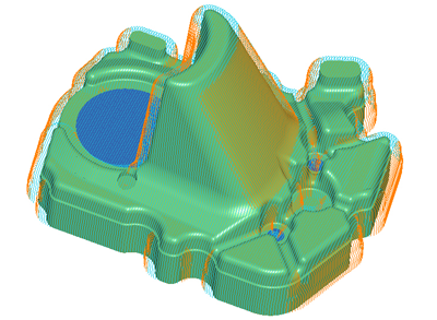
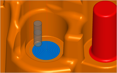
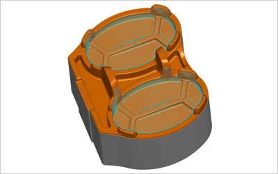
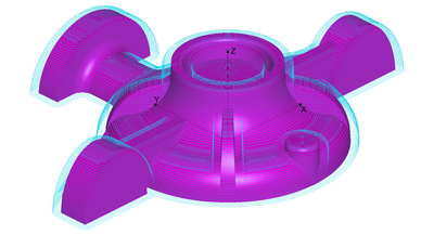
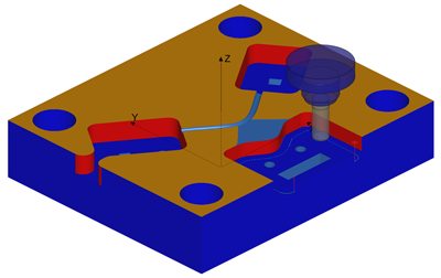
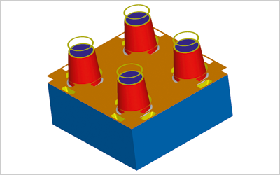
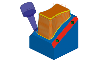
Area Clearance Roughing

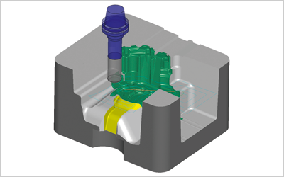
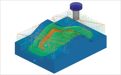
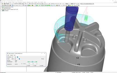
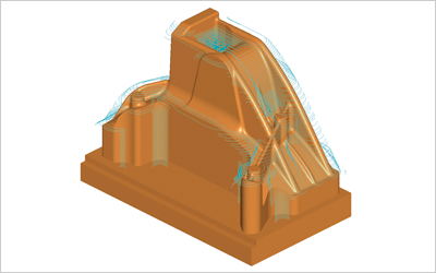
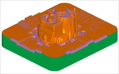
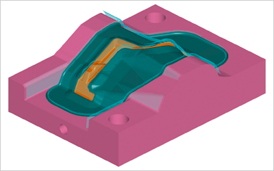
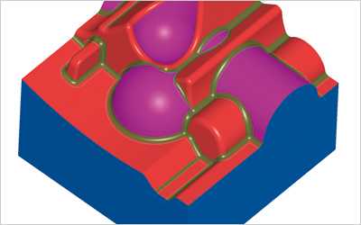
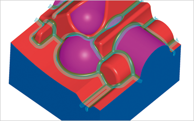
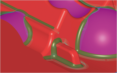
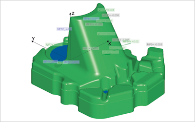
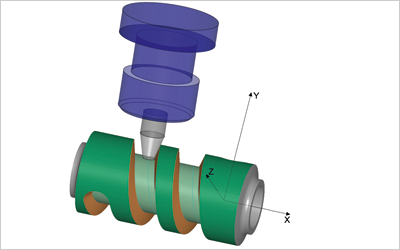
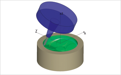
NCG CAM’s automatic roughing of surface data is suitable for all types of 2D or 3D forms, creating an optimised, smooth cutting motion for high speed machining (HSM) while maintaining part accuracy, cutting tool life and machine tool life. All cutters and tool-holders are collision protected to maximise efficiency and stock model visualisation of the machined part is available at every stage of the manufacturing process.

Read more ...

Core Roughing

NCG CAM has an additional routine for roughing which is ideal for core forms, where the machinist wants to rough away the material by machining from the outside, whilst maintaining climb milling. All toolpaths start in fresh-air at the given Z-depth, and work into the middle.

Read more ...

Raster Roughing & Zig-Zag Roughing

Zig-zag roughing in NCG CAM will take linear cuts across the job at fixed Z levels, similar to area clearance or core roughing passes. As these passes are linear, there is far less data involved and fewer changes of machine directions. At each level a profile pass is performed to remove the cusps around the parts profile at that level, before moving down to the next Z-level.

Read more ...

Stock Models

Stock models can be created from one or more toolpaths, which can be 3, 3+2 or 5 axis, or a combination. Stock models can be used for the visualisation of the machined part on the screen, eliminating any costly test cutting.

Read more ...

Horizontal Area & Horizontal Core Machining

Horizontal area passes are used to finish machine flat surfaces more efficiently by using flat bottom cutters. Horizontal area passes are aimed towards cavities, while horizontal core passes start off the block and machine in from the side making them more suitable for core forms, whilst extending tool life.

Read more ...

Spiral Machining

This creates an archimedean spiral toolpath from a given focal point, generating a constant contact as it machines within a given boundary.

Read more ...

Radial Machining

Similar to spiral machining, radial machining also starts from a focal point, providing the user with the ability to create radial passes. Some extra options include the ability to stop short of the centre where the radial passes become very dense.

Read more ...

3D Constant Offset Machining

The constant offset machining strategy is used for maintaining a constant equidistant step-over from one tool pass to the next, irrespective of the slope angle of the part.

Read more ...

Pencil Milling

The pencil milling routine is to finish corners which might otherwise have cusp marks left from previous machining operations.

Read more ...

Parallel Pencil Milling

Parallel pencil milling is an extension of pencil milling, in that the user can determine the number and step-over of multiple-passes either side of the pencil toolpath.

Read more ...

Boundary Machining

Boundary machining, machines along an open or closed boundary profile. A negative machining thickness can be used to machine at constant depth below the surface being machined and can be used in conjunction with cutter contact angles.

Read more ...

True Surface Machining

NCG CAM machines using triangulations as standard, which are quick to calculate and check against for gouge free machining. True surface machining is optional for users to select, should they wish. Machining the surfaces spaces the points in the NC Tape file more uniformly, giving a better / smoother machine movement on some machine tools. However, the calculations to ensure the machining is gouge free will take longer in most cases.

The better the surface finish means less hand polishing, which saves time and money, it also reduces any mis-match / flash caused by polishing rolling/belling corners.

Read more ...

Surface Analysis

The curvature function allows the user to quickly find out what the smallest radii is on the part to aid cutter selection. Internal and external radii are filterable and the radii range is user definable. For quick identification this is done graphically using a colour overlay to the surfaces and the cursor tool tip provides an accurate size.

Read more ...

Combined Passes – Waterline & Constant Stepover

The curvature function allows the user to quickly find out what the smallest radii is on the part to aid cutter selection. Internal and external radii are filterable and the radii range is user definable. For quick identification this is done graphically using a colour overlay to the surfaces and the cursor tool tip provides an accurate size.

Read more ...

3+2 Axis Machining

3+2 multi-axis machining has an easy to use graphical interface, including being able to snap to the surface normal for machining.

Read more ...

Rest Areas Options

NCG CAM has rest area machining options on all the finishing routines, such as waterline, raster, spiral, radial, constant step-over, parallel pencil passes, corner offset passes, morphed and boundary passes.

Read more ...

Edit Surface Trimming Holes & Ruled Surface

When machining components or moulds, it is sometimes necessary to remove holes or other apertures from surfaces to enable more efficient manufacture. NCG CAM has functionality which will enable the user to remove individual holes, even on doubly curved surfaces, or remove the complete inside trimming edges as shown right.

Read more ...

Hole Detection & Drilling

NCG CAM has automatic hole detection for all holes, chamfers and cones that form part of the same hole composite. When detecting holes they can be filtered by minimum or maximum diameters, depth, angle (tool axis) colour.

Read more ...

Electrode Machining

Within NCG CAM there is a spark-gap variable that can be used to aid the manufacturing of electrodes for EDM. By using the spark-gap variable in conjunction with the marcos, the user can make another electrode with different spark-gap with very little input.

Read more ...

Shop Floor Documentation

Tool sheets are automatically created in XML / HTML format and have the option to include graphics. The tool sheets are vital if the part is to be machined by someone other than the person who programmed it. For parts that are machined quite often, (a perfect example being a forge die that may be on the machine for a re-cut 2 or 3 times a week), the tooling sheet ensures the operator knows which tool and tool size machines each part.

Read more ...

Part Inspection

NCG CAM has an inspection module which allows the machined part to be inspected while still on the CNC machine tool.

This is particularly useful for large components which take valuable time to take off the machine tool, send to the inspection department, and set-up again if re-machining is required. Other applications that the part inspection is useful for complex 3D doubly curved components which can only be inspected to the original surface model, or for the checking of spark-erosion electrodes for accuracy of negative spark-gap allowances prior to being used in the spark erosion process.

Read more ...

Swarf Machining (5-axis Add-on Module)

In NCG CAM using swarf machining allows the side of the cutter to be used, keeping it orthogonal with the surface; a lead/lag angle can still be applied if needed. With swarf machining it is also possible to offset the passes along the tool-axis.

Read more ...

Machine Tool Simulation (5-axis Add-on Module)

The machine tool simulation allows the user to simulate the machine movement. This is generally very important for 5-axis toolpaths, where it is often difficult to visualise the real position of the machine when animating the toolpath. By running the toolpath through the machine simulation, you can be sure there will be no collision between the machine head and the bed/table of the machine.

Read more ...

Advanced 5-axis Toolpaths for Mould & Die Machining (5-axis Add-on Module)

Tool axis control allows the user to have some control of how the tool tilts:
• Tilt through or away from a point
• Tilt through or away from a curve
• Full gouge avoidance of cutter and holder
• Minimise side tilt to avoid collision
• Lead/lag and tilt angles available
• Minimal tilt to avoid holder collisions
• 3, 4, or 5-axis options. When selecting 4-axis, the user has
to say which axis the 4th axis rotates about.

Read more ...

Search

We use cookies on our website. Some of them are essential for the operation of the site, while others help us to improve this site and the user experience (tracking cookies). You can decide for yourself whether you want to allow cookies or not. Please note that if you reject them, you may not be able to use all the functionalities of the site.