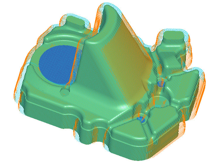
Raster toolpaths are used for finishing in conjunction with steep and shallow cutter contact angles and another machining routine, typically waterline.
The raster toolpath would have a cutter contact angle of around 0° – 40° and waterline 30° – 90°. This approach uses the best machining combination for finishing complex 3D surfaces and can be used on older CNC milling machines or high speed machines alike. Raster passes can be constrained to a boundary or by the selected surfaces.
Perpendicular raster toolpaths are used for finish machining the whole component with a constant surface finish and at the same time maintain a climb milling direction. Perpendicular as it suggests, machines using raster passes in one direction. It omits passes on the steep faces that are parallel with the cutting direction and then fills in the gaps with another raster toolpath at 90° to the previous, thus maintaining surface finish and climb machining.
Linking options include one-way and bi-directional, plus options for down-milling (for 3D machining with carbide-insert cutters) and up-milling (for 3D finishing with solid carbide ball cutters).